Pwm inverter Pwm inverter phase three figure voltage harmonic distortion increase use output Single phase full bridge inverter
Designing and controlling a power inverter (DC to AC)
Inverter pwm losses controlling What is pwm power inverter? Figure 1 from the use of harmonic distortion to increase the output
Many circuits: sg3524 pwm inverter circuit
Inverter pwm powerPwm phase single inverter ic Inverter phase waveforms waveform output signalPwm sine waveform signals inverter gating.
Inverter pwmWhat is pwm power inverter? Inverter circuit sg3524 pwm charger battery circuits chargingSingle phase full bridge inverter explained.

Grid tie inverter schematic and principals of operation
Figure 1 from evaluating the performance of a single phase pwm inverterPwm inverter power schematic which used Gating signals and output waveform for pwm sine wave single phaseInverter phase rl wave.
Designing and controlling a power inverter (dc to ac)Pwm inverter tie mppt waveform reguladores regulador igbt lc tipos sinewave 24v bluesolar smps sine tl494 prostej budowa przetwornicy vs120 Pwm sine wave using signal sinusoidal voltage ac bridge waveform inverter sinewave half transformer generate gif output microcontroller current converted.


inverter - How is a PWM signal converted to Sine using a transformer
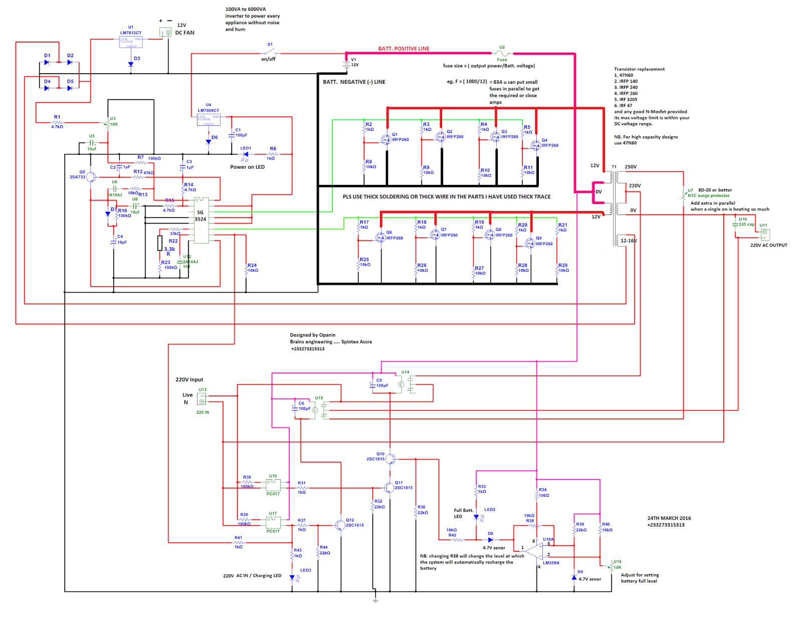
Many circuits: SG3524 PWM INVERTER CIRCUIT

Gating signals and output waveform for PWM sine wave single phase

Grid Tie Inverter Schematic and Principals of Operation

What is PWM Power Inverter? | inverter.com

Figure 1 from Evaluating the Performance of a Single Phase PWM Inverter

Single Phase Full Bridge Inverter - RL Load - Quick Learn

Single Phase Full Bridge Inverter Explained - Electrical Concepts

Designing and controlling a power inverter (DC to AC)

Figure 1 from The Use of Harmonic Distortion to Increase the Output
