A real time clock design (ds1307) with a pic microcontroller How to build a real-time clock circuit with a ds1307 chip Arduino clock time real ds1307 rtc module using circuit diagram interfacing
Interfacing PIC16F84A with DS1307 real time clock
Arduino real time clock using ds1307 rtc module Oled ssd1306 circuit ds1307 clock real time diagram display terminals grounded connected together Clock circuit digital real time diagram rtc seekic schematic figure
Real time clock with alarm option using at89s52 and ds1307 ic
Interfacing pic16f84a with ds1307 real time clockHow to use real-time clocks with the raspberry pi Circuit clock real time ds1307 rtc breadboard schematic build chip oscillator crystalRtc circuitbasics configure.
Ds1307 clock time real circuit diagram arduino interfacingReal time clock with timer Ds1307 circuit real clock time rtc vdd interfacing schematic diagram supplied 5v pins mustDs1307 real time clock module.

Ds1307 clock time real schematic module i2c rtc electronics lab acoptex
Real time clock(how to interface ds1307 rtc to at89s52 microcontroller)How to build a real-time clock circuit with an arduino How to use a real-time clock module with the arduinoMake real time digital clock using atmega328p-pu micro controller or.
Ds1307 time clock rtc real circuit simple ccs using lcd clear used buttonsReal time clock ds1307 interfacing with arduino Circuit ds1307 clock time real rtc fig electro interface microcontrollerClock circuit ds1307 time real 16f88 segment circuits rtc diagram microcontroller electronic projects seven only using.

Ds1307 real time seven segment clock circuit
Real time clock with pic16f877a, ssd1306 oled and ds1307Ds1307 rtc circuit Timer hackster circuitReal time clock.
Real time clock with alarm option using at89s52 and ds1307 icClock circuit ds1307 microcontroller Arduino clock time module real diagram rtc circuit use wiringDs1307 rtc module.

Clock real time circuit seekic diagram control
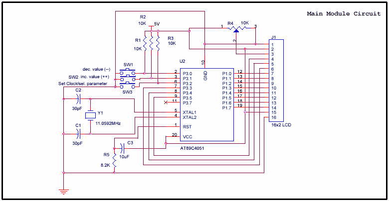
At89c4051 digital real time clock circuitClock time ic real ds1307 microcontroller project rtc mikroc diagram circuit micro using pic Real time clock using pic16f877a and ds1307 rtcCircuit arduino clock time real rtc breadboard schematic module analog straightforward connections physical pretty power.
Alarm ds1307 microcontroller engineersgarage proteus arduino lcd rtcClock circuit digital diagram arduino real time atmega328p using micro make .


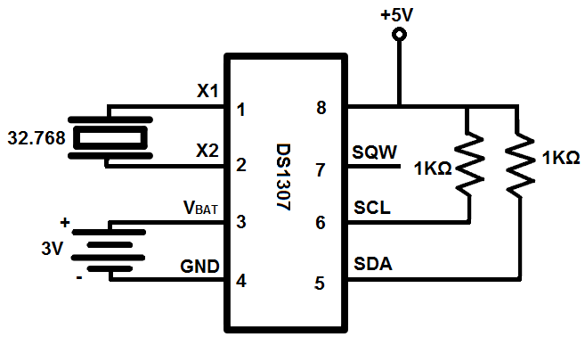
How to Build a Real-time Clock Circuit with a DS1307 Chip

AT89C4051 Digital Real Time Clock Circuit - Electronic Circuit

Arduino Real Time Clock using DS1307 RTC Module

How To Use Real-Time Clocks With the Raspberry Pi - Circuit Basics

How to Use a Real-time Clock Module with the Arduino - Circuit Basics

Real Time Clock with Alarm Option using AT89S52 and DS1307 IC

Interfacing PIC16F84A with DS1307 real time clock

DS1307 Real Time Clock Module - Electronics-Lab.com
