Rlc bandpass vout amplitude frequency Rlc consider Rlc circuit series problems analysis example electrical resonance circuits figure frequency equation assignment help capacitive
Solved Consider the RLC circuit shown below. Choose values | Chegg.com
Rlc resonance lcr circuitos circuits circuito physics emf inductance schaltung topperlearning farad capacitance Solved consider the rlc circuit shown below with input the Rlc bandpass parallel eeweb
Rlc phasor impedance figure
Simulation of currents in the rlc circuit under voltage clamp (a) rlcBasic tutorial lesson 2: time and frequency domain analysis of an rlc Circuit rlc input shown consider below equation voltage differential output has been chegg show problem solved describes answer transcribed textWhat is rlc series circuit?.
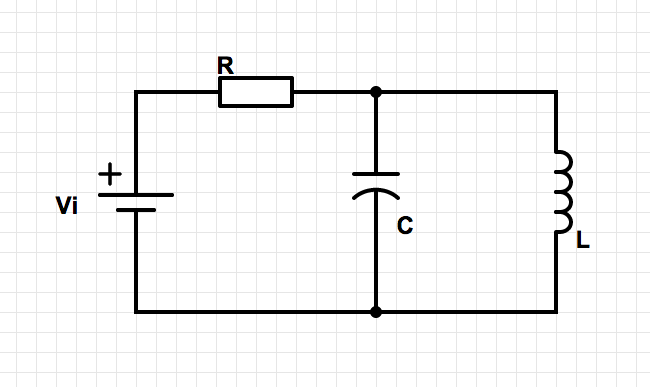
Rlc phasor impedance globeRlc filter bandpass circuit schematic circuitlab created using Chapter 21: rlc circuitsDiagram of an rlc electric circuit used as a bandpass filter. the.

Serie rlc schaltung und rlc serienschaltung analyse
Solved consider the rlc circuit shown below. choose valuesLow-pass filter Circuit rlc filter ratio damping solved expert answerBand rlc pass stop filters.
Electronic turn: resonance in electrical circuits : deriving thePass low rc filters rl filter rlc circuits circuit stratocaster high frequency inductive rarely visited off capacitive Rlc band stop filters and band pass filtersRlc clamp waveform currents voltages recording.

Series rlc circuit
Rlc circuitFilters: use rc, rl, or rlc circuits? Rlc circuit series analysis electrical diagram gif will initial conditions taken using electricalacademiaCircuit analysis.
Rlc circuit inductor series electrical voltage across capacitor factor resistor simple transfer model torRlc circuits chapter current frequency voltage Parallel rlc bandpass filterRlc series circuit analysis.

Filter pass low rlc electronics circuit lpf formulas
Rlc filter frequency domain lesson analysis basic tutorial time emagtech wiki .
.


What is RLC Series Circuit? - Phasor Diagram & Impedance Triangle

Diagram of an RLC electric circuit used as a bandpass filter. The

Low-pass filter - Electronics - BasicTables

circuit analysis - RLC bandpass filter - Electrical Engineering Stack

Solved Consider the RLC circuit shown below. Choose values | Chegg.com
Parallel RLC Bandpass Filter - EEWeb

Basic Tutorial Lesson 2: Time and Frequency Domain Analysis of an RLC

Filters: Use RC, RL, or RLC circuits? | The Rarely Visited Blog
